Spiral tower drying machine
Short Description:
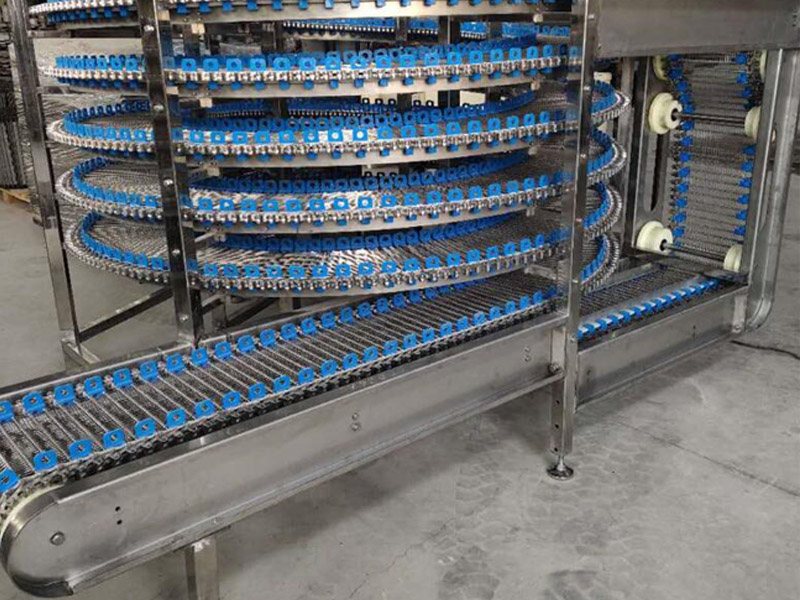
Drytech Spiral type automatic feeding and discharging drying Machine
Technical field
The invention relates to the technical field of drying equipment, in particular to a spiral type automatic feeding and discharging drying room.
Background technique
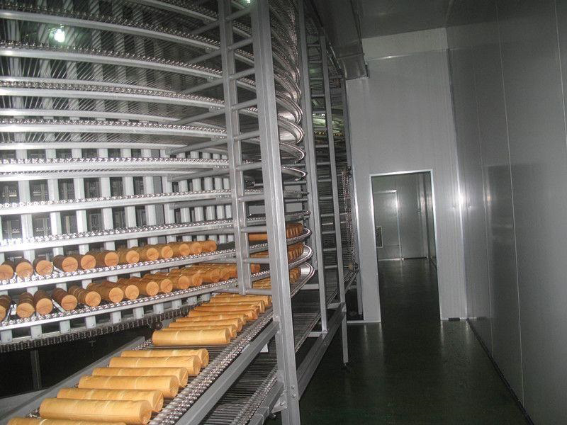
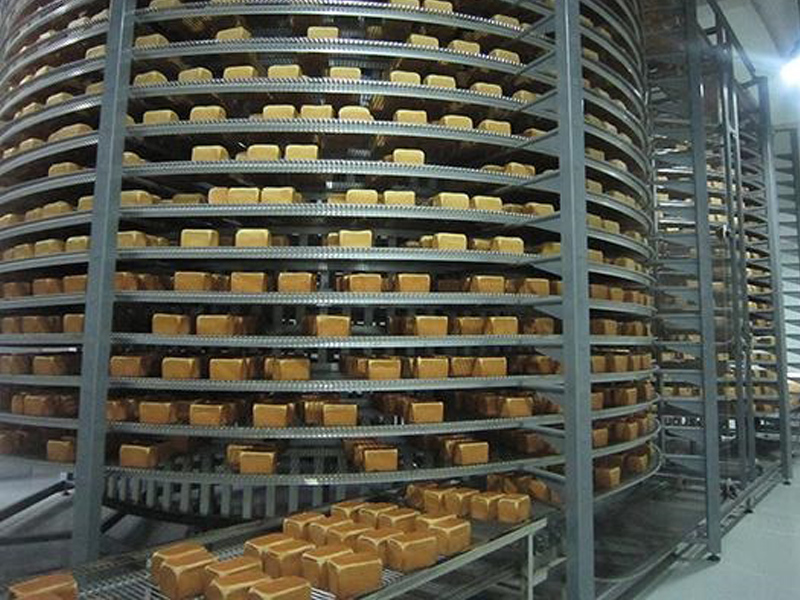
The storage, production and processing of food, fruits, vegetables, and grains need to be dried. Commonly used drying methods include traditional natural drying under the sun, the production line is dried in an oven, and various drying rooms are used. In the prior art, when a drying room is used for drying, tray drying or belt drying is mostly used. Tray drying, that is, the materials to be dried are manually loaded on multiple trays. The trays are placed on each layer of the movable drying rack, and the drying rack is pushed into the drying room for drying, and then pulled out after the end. This method wastes a lot of labor and time, and the drying efficiency is low, which cannot meet the needs of automated production; belt drying uses a transfer method that vertically drops from the upper layer to the lower layer, and the material is passed down to the bottom layer in the opposite direction. The method occupies a large area and requires more workshop space.
In addition, facing the drying of large quantities of materials, there is an urgent need for a drying room with high drying efficiency, small space occupation, energy saving and environmental protection.
Summary of the invention
In view of the above-mentioned defects and deficiencies in the prior art, the present invention proposes a screw-type automatic feeding and discharging drying room, through the combination of an air-energy heat pump drying and dehumidification integrated machine and a vertical screw conveyor, which greatly saves floor space And space, automatic control of the drying process, high efficiency, energy saving and environmental protection.
The above objectives of the present invention are achieved through the following technical solutions:
A screw type automatic feeding and discharging drying room includes a drying room, an air-energy heat pump drying and dehumidifying integrated machine arranged on the left side of the drying room, and a vertical screw conveyor arranged on the right side of the drying room. The side wall of the drying room is provided with an inlet and an outlet, the input end of the vertical screw conveyor extends outside the inlet, the output end extends outside the outlet, and the input end A variable frequency speed regulating motor is connected, the air energy heat pump drying and dehumidifying integrated machine, and the variable frequency speed regulating motor are electrically connected to the PLC controller outside the drying room.
Further, the air-energy heat pump drying and dehumidifying integrated machine is provided with an evaporator on the left side of the box and a condenser on the right side. The left side wall of the drying room has an inlet opening where the position of the evaporator matches. The air outlet, the evaporation fan of the air energy heat pump drying and dehumidification integrated machine is adapted to pass through the air inlet, and the right side wall of the box of the air energy heat pump drying and dehumidification integrated machine is opened at a position matching the position of the condenser There is an air supply port, and a condensation fan is provided on the left side of the condenser opposite to the air supply port.
Preferably, a filter screen is provided outside the air inlet.
Preferably, the evaporating fan and the condensing fan are both high-temperature-resistant axial flow fans.
Further, the lower part of the right side wall of the box of the air energy heat pump drying and dehumidification integrated machine is provided with a return air outlet, and the lower part of the front side wall and the corresponding side wall of the drying room are provided with air outlets at corresponding positions. The box of the integrated drying and dehumidification machine is provided with a dehumidification heat exchange device, the input end of the dehumidification heat exchange device is connected to the return air outlet through a pipe, and the output end is connected to the air outlet through a pipe.
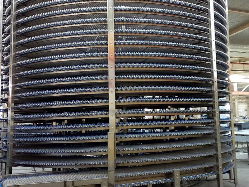
Further, the vertical screw conveyor is set up for bottom in and top out, the feed inlet is located at the lower part of the right side wall of the drying room, and the material outlet is located at the upper part of the right side wall of the drying room.
Further, the air supply port is located on the upper part of the right side wall of the box of the integrated air energy heat pump drying and dehumidification machine.
Preferably, a temperature and humidity sensor is provided in the drying room, and the temperature and humidity sensor is electrically connected to the PLC controller.
Preferably, the drying room is a polyurethane insulation board room.
Compared with the prior art, the technical solution of the present invention has the following beneficial effects:
The invention adopts an air-energy heat pump drying and dehumidification integrated machine, drying and dehumidifying are performed simultaneously, and heat energy can be recovered, and the drying process is energy-saving and environmentally friendly; adopts a vertical screw conveyor and is driven by a variable frequency speed regulating motor, which greatly saves space Area and space, continuous transportation of materials, stable and efficient transportation; PLC programmable control is used to control the drying time, temperature and humidity according to the drying requirements of different materials, and the drying process is automatically controlled with high efficiency and can meet mass production.